I am still trying to figure out the best way to document this whole process. When it comes to these projects, I will work on something for a bit and then see a “squirrel” and jump to something else. The benefit of documenting the process here, with pictures, is that you can’t tell the order in which I did things – I can edit and rearrange and you are none the wiser.
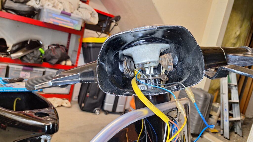
Let’s take a look at the handlebars before I start the teardown process. This helps to show YOU what it looks like before, and helps ME to remember what it is supposed to look like when I am finished!
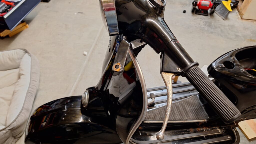
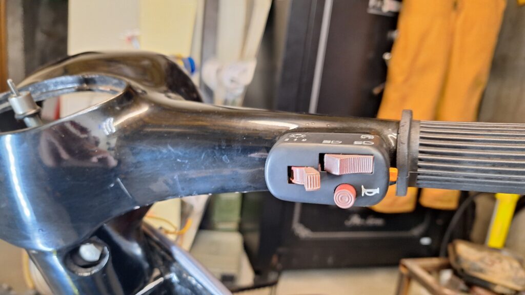
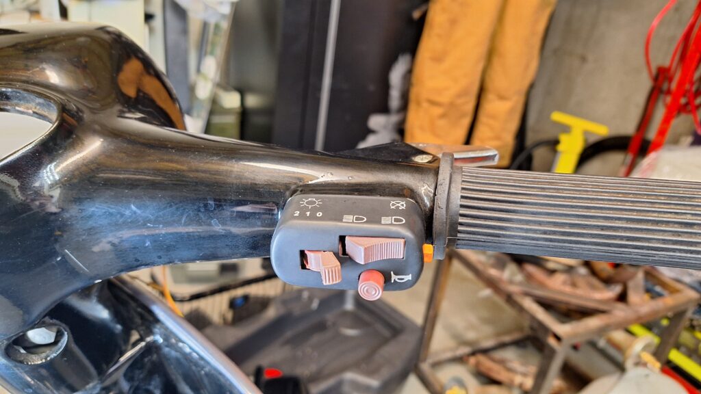
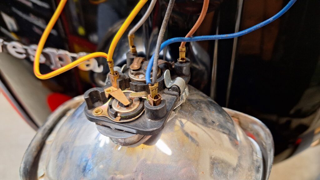
Switch
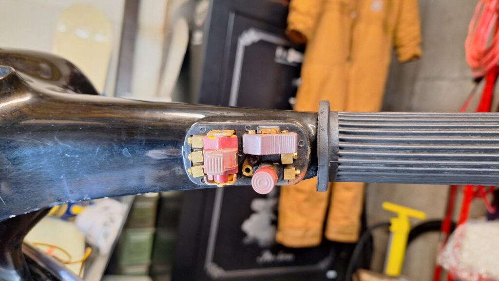
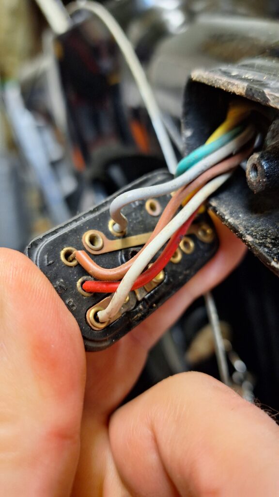
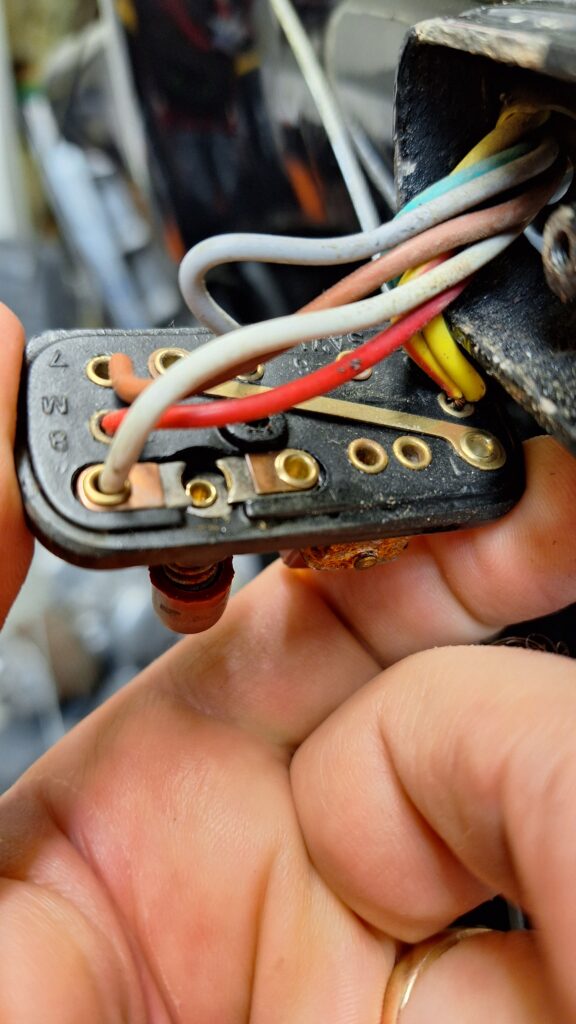
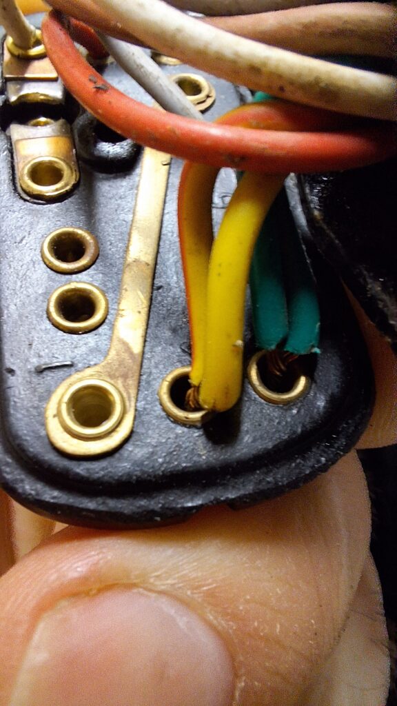
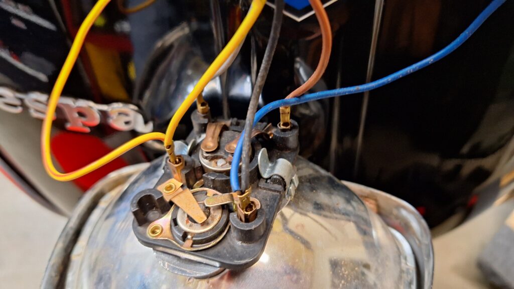
The existing switch functioned well, but I wanted to freshen it up a bit. I was confused about the kill button because there didn’t seem to be one, but once I popped the cover off, I discovered the button INSIDE the case. For the purpose of a good before photo, I replaced it before snapping these photos. (It is the bright orange button on the right side – bright because it was protected from the sun inside the switch for all those years.)
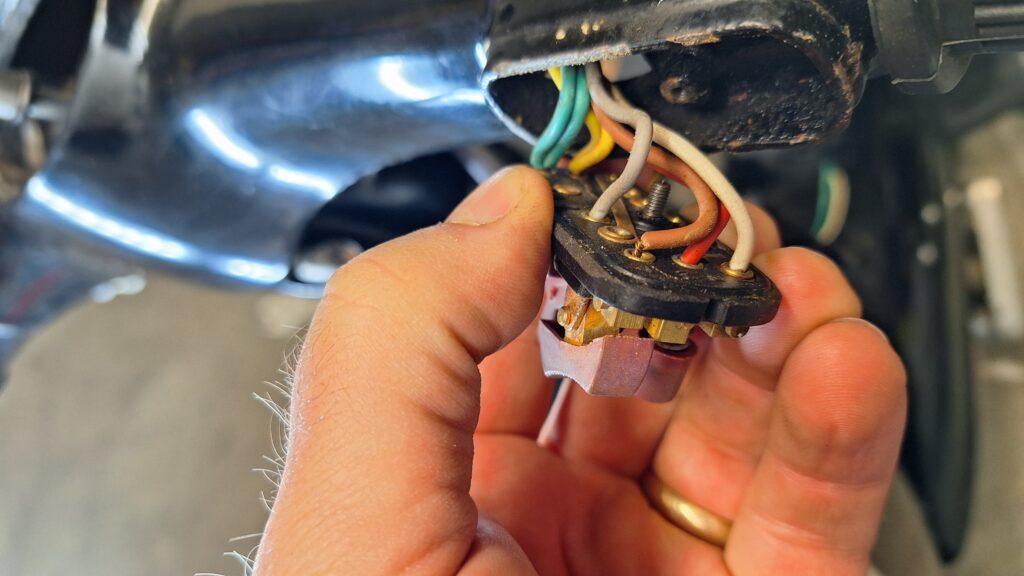
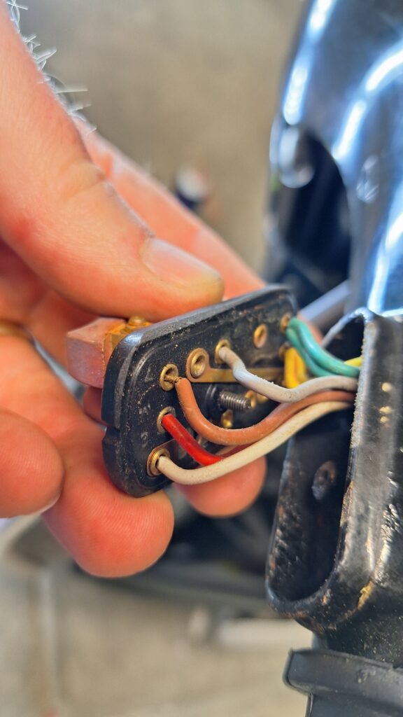
The switch is fastened with one small screw in the center of the switch unit. The curvature of the wires were tough to work loose and through the handlebar tubes.
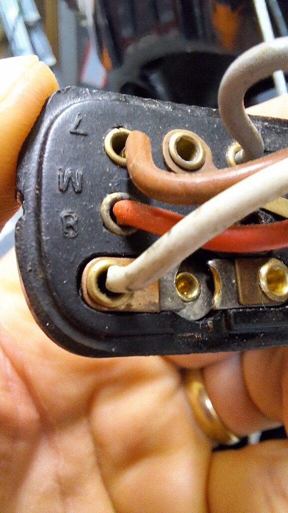
This also a great example of “photo evidence” that I will be able to use when I wire up the new switch.
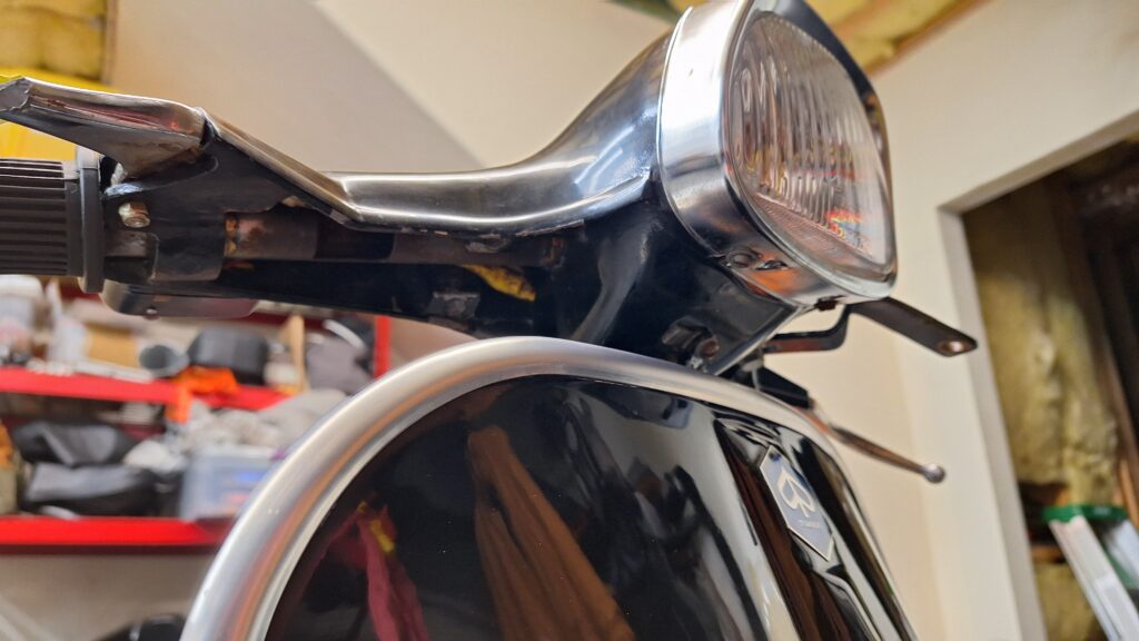
Headlamp
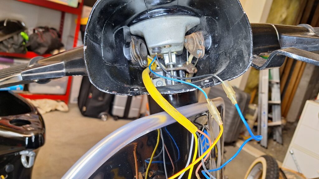
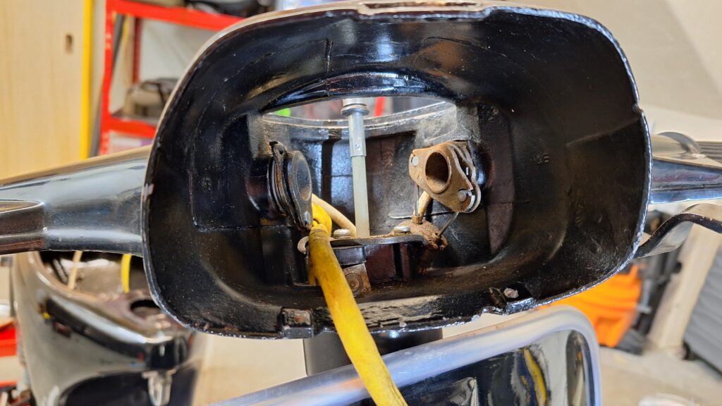
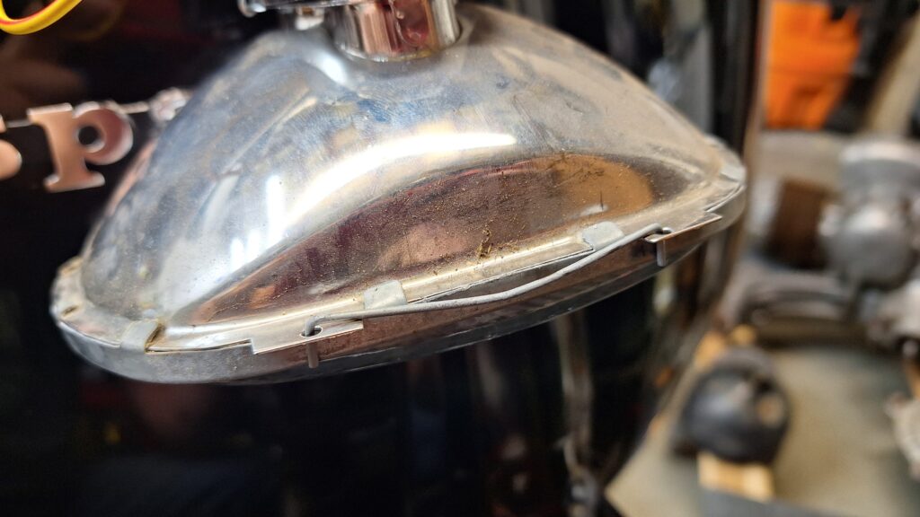
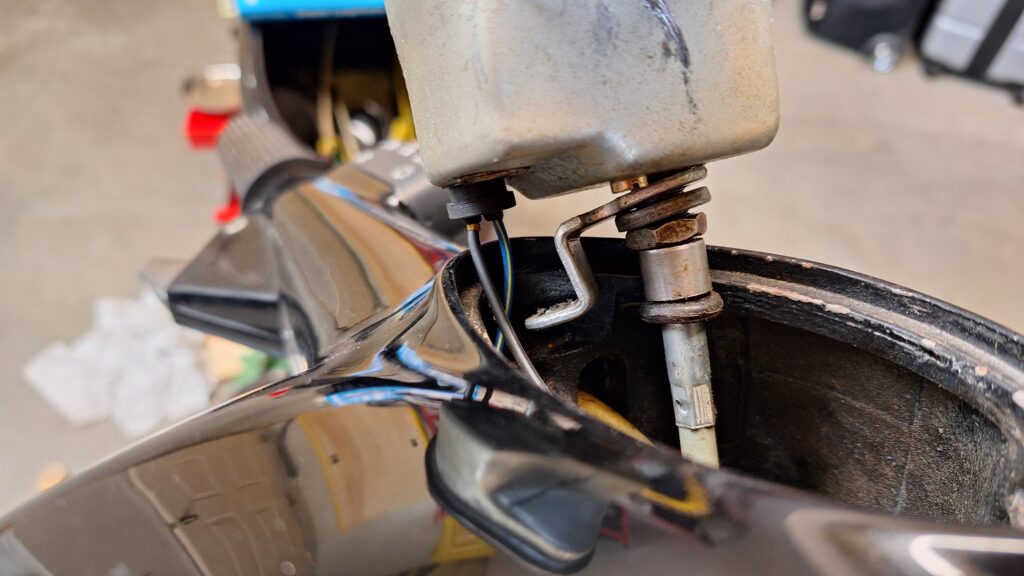
The headlamp is removed with two small screws that secure the chrome trim to the bulb housing. To access the screws, you have to swing the handlebars full left and then full right to be able to loosen using a small screwdriver. From there, the bottom of the trim tilts out and then removed by lifting a tab out of a slot in the handlebar frame. You might be able to see it in one of the photos below.
The headlamp then falls forward and can be removed by detaching the spade connectors from the bulb housing. Again, these photos will help at reassembly time.
You can also see the back/bottom of the speedometer. One long screw will loosen the speedo from the handlebar housing. From there, the speedometer cable (silver, knurled nut at the bottom) can be unscrewed and the speedo is free. As a side note, I have another Piaggio scooter that is a Euro model and has the speed marked in kilometers per hour and not miles per hour. To avoid having to do mental math to ensure I am not speeding, I wanted to replace the speedo with a “MPH” version and was able to find a replacement (MPH) that is shipping from overseas and should be here in about a month. I’ll be sure to share photos of it during reassembly.
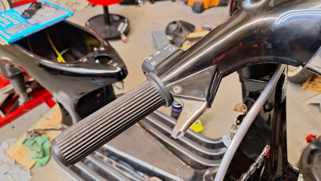
One other thing to note in the picture “looking in” with the headlight removed – you can see the ends of the throttle tube and shifter tube. There are 2 cables on the right – throttle and front brake and 3 cables on the left – upshift, downshift, and the clutch. I plan to replace all of the cables with modern, Teflon-lined cables to give Christy a fresh start with strong and smooth cable controls. More on these later.
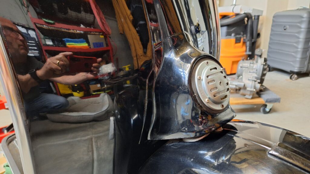
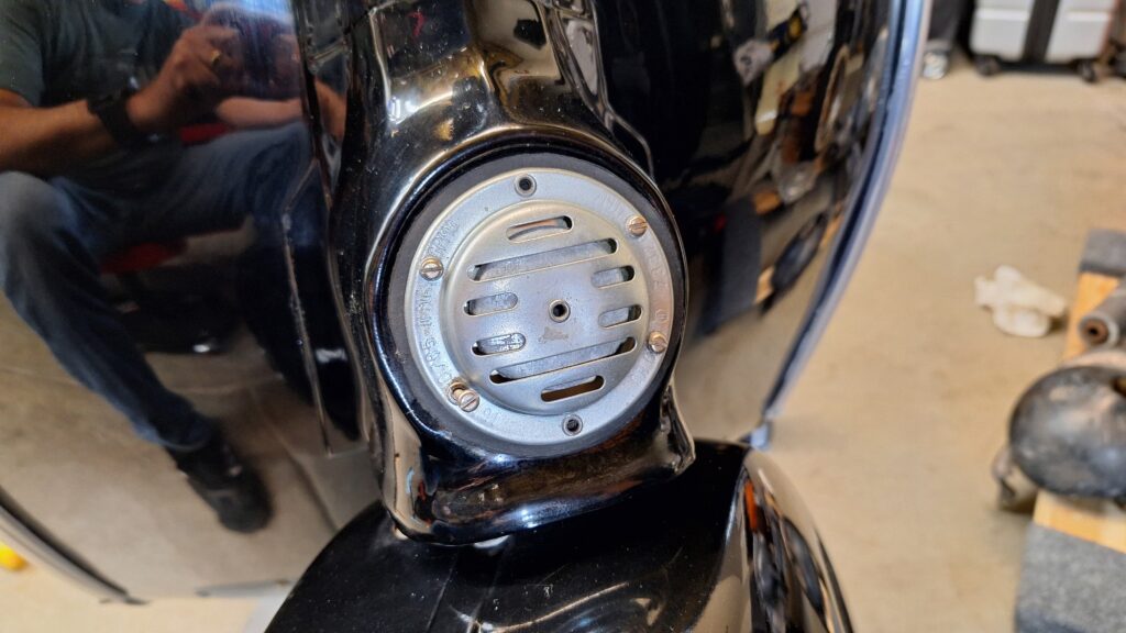
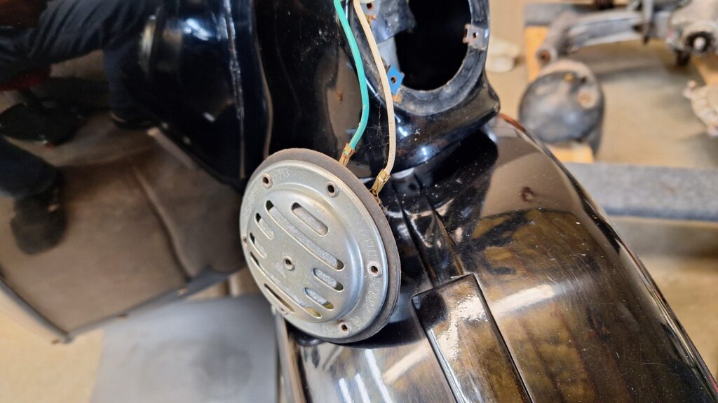
Horn
Not much to show with the horn. Four screws and two spade connectors and it is free. The horn only works with the engine running, as there is no battery. Once the engine is running again, I will test it to make sure it functions. I do plan to replace it with a Vespa OEM product that is chrome finished. I just need to test it to determine whether it is AC or DC coming through those wires.